Eval Kit for TFT 10.1" 1024x600, CAN Bus interface with CUSTOMIZABLE CAN ID & GPIO Support, 32MB Flash Memory, 400cd/m², Wide View Angle (IPS), Capacitive touch panel (GG)
DESCRIPTION
WL0F00101000JGAACSA05-FC is a 10.1-inch Smart Display from the CAN series, designed as a slave device. It is controlled via CAN bus commands from a master device to render content on the screen and return touch event data with protocol objects. Integrated with a standard TFT module WF101-1024600JL#0P8-FC and a 4-layer PCBA, this model comes with built-in firmware, making it a powerful yet cost-effective solution for rapid project development.
Key Features:
- +12V power supply input, with a power consumption of approximately 6W.
- Self-testing function after booting.
- CAN bus communication interface for easy integration.
- Supports custom CAN ID protocol with a default baud rate of 250Kbps.
- 32MB external flash memory for storing fonts and Object Dictionary Data.
- Projected Capacitive Touch (PCAP) support for enhanced touch responsiveness.
- Embedded buzzer, controllable by the master device.
- Flexible HOST platform options: Computer (with USB-to-CAN Dongle), MCU, or Raspberry Pi (with PiCAN2).
- General-purpose GPIO support for additional custom functionality.
- Design the UI without writing a line of code by WINSTARGUI builder! (►Link to GUI Builder Introduction)
- Powered by STM32F series MCU and compatible with STMicroelectronics’ software development tools.
- Extended memory management features, including:
- Maximum 255 objects per page (compared to 64 objects in the 16MB version).
- Maximum 1000 total objects (compared to 500 in the 16MB version).
- Up to 64 pages (compared to 30 pages in the 16MB version).
- Dynamic memory allocation support for improved flash storage management.
DRAWING
SPECIFICATIONS
General Specifications
| Item | Standard Value | Unit |
|---|
| Operating voltage |
8V~28V dynamic |
Vdc |
| Communication Interface |
CAN bus |
Vpp |
| MCU |
STM32F746 |
N/A |
| Flash Memory |
32 |
MB |
| LCD display size |
10.1 |
inch |
| Dot Matrix |
1024 x RGB x 600(TFT) |
dots |
| Module dimension |
248.8(W) x 143(H) x 23.2(D) |
mm |
| Active area |
222.72 (H) x 125.28(V) |
mm |
| Dot pitch |
0.2175(W) x 0.2088(H) |
mm |
| Brightness |
Min:300;Typ:400 |
| LCD type |
TFT, Normally Black, Transmissive |
| View Direction |
85/85/85/85 |
| Aspect Ratio |
16:9 |
| Touch Panel |
Projected Capacitive Touch Panel (PCAP) |
| Surface |
Glare |
Absolute Maximum Ratings
| Item | Symbol | Min | Typ | Max | Unit |
|---|
| Operating Temperature |
TOP |
-20 |
- |
+70 |
℃ |
| Storage Temperature |
TST |
-30 |
- |
+80 |
℃ |
Electrical Characteristics
| Item | Symbol | Condition | Min | Typ | Max | Unit |
|---|
| Supply Voltage |
VCC |
- |
8 |
12 |
28 |
V |
| Supply LCM current |
I(mA) |
- |
- |
530 |
- |
mA |
BOM
| Item | Description |
|---|
| LCM |
WF101-1024600JL#0P8-FC |
| PCBA |
SV10010R100JB00N0108 |
Interface Pin Function
CON1 definition
| Pin | Symbol | Function | Remark |
|---|
| 1 |
VIN |
Power supply12V input |
Input |
| 2 |
GND |
Power supply GND input |
Input |
| 3 |
CAN_H |
CAN bus D+ |
I/O |
| 4 |
CAN_L |
CAN bus D- |
I/O |
| 5 |
GND |
Power supply GND input |
GND |
| 6 |
GND |
Power supply GND input |
GND |
| 7 |
Reserve |
USB_D- |
Reserve |
| 8 |
Reserve |
USB_D+ |
Reserve |
| 9 |
NC |
- |
- |
| 10 |
Reserve |
USART RX interface(Reserve) |
Reserve |
| 11 |
Reserve |
USART TX interface(Reserve) |
Reserve |
| 12 |
GND |
Power supply GND input |
GND |
| 13 |
+12V |
Power supply12V input |
Input |
| 14 |
NC |
- |
- |
| 15 |
NC |
- |
- |
| 16 |
GND |
Power supply GND input |
Input |
CON2 definition
| Pin | Symbol | Function | Remark |
|---|
| 1 |
+3V3 |
3.3V power for JTAG interface |
Output |
| 2 |
SWCLK |
CLK pin for JTAG interface |
Input |
| 3 |
GND |
GND for JTAG interface |
Output |
| 4 |
SWDIO |
Data pin for JTAG interface |
I/O |
| 5 |
NRST |
Reset pin for JTAG interface |
Input |
| 6 |
GND |
GND |
Output |
| 7 |
IO_8 |
(PA0) for system Resume
from suspend (Reserve) |
WKup,ADC,Timer,Event,I/O |
| 8 |
REST |
Reset (active Low) |
I |
| 9 |
IO_0 |
ADC,DAC,Timer,Event,I/O |
PA5 |
| 10 |
IO_1 |
ADC,Timer,Event,I/O |
PA6 |
| 11 |
IO_2 |
ADC,Timer,Event,I/O |
PA7 |
| 12 |
IO_3 |
RST,Timer,Event,I/O |
PA8 |
| 13 |
IO_4 |
RST,Timer,Event,I/O |
PC13 |
| 14 |
IO_5 |
ADC,Timer,Event,I/O |
PB11 |
| 15 |
IO_6 |
RST,Timer,Event,I/O |
PA15 |
| 16 |
IO_7 |
RST,ADC,Event,I/O |
PD11 |
Display Usage
Functional description
Smart Display can be used to display the coordinate, status and data information provided by the connected HOST device. Customers can configure the position coordinates they want to display in normal operation mode
The Display is designed to be easily connected to a controller network, and to use the register type of Holding Register.
Splash Screen
The default splash image is shown below.
This product is produced as a generic product. If you require a custom splash image for your application, contact us to discuss
Default Selection
Press the preferred application and hold for 3 seconds for the first time power on.
Acquisition of Displayed Data
Smart Display uses the Modbus protocol to get and send the data.
On Config mode, customers can set the coordinates or type of objects; On Display mode, customers can send and get data of objects.
Configuring the Display
Winstar Smart Display RS-485 series offers an out-of-the-box Modbus development experience that will lower customers' development costs and speed time-to-market expectations.
The Smart Display can use wide-temperature are designed to support control applications in harsh operating conditions, which designed to be connected to a variety of different situation combinations, such as automotive, marine, power generation and oil-and-gas.
The Smart Display comes with standard UI objects to get customers project off the ground quickly. If customers need custom UI objects support, our engineers are here to help. Send over your contents in PNG/JPG format, we will send over a new set of UI objects within 3~5 working days.
The Smart Display is defined as a slave device, which is controlled by master device via RS-485 command to render display content on the display screen and return touch event data with protocol objects.
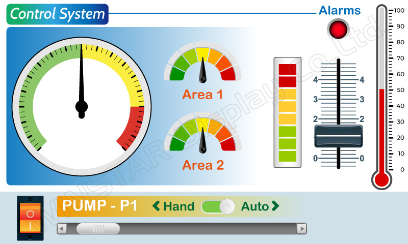
Example Screen Layout (Industry application)
Example Layout
The screen layout described in this section is intended to demonstrate the settings of screen items that can be used in an industry application situation.
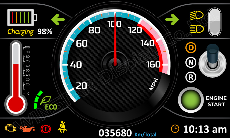
Example Layout (Vehicle automotive)
The screen layout described in this section is intended to demonstrate the settings of screen items that can be used in a vehicle automotive situation.
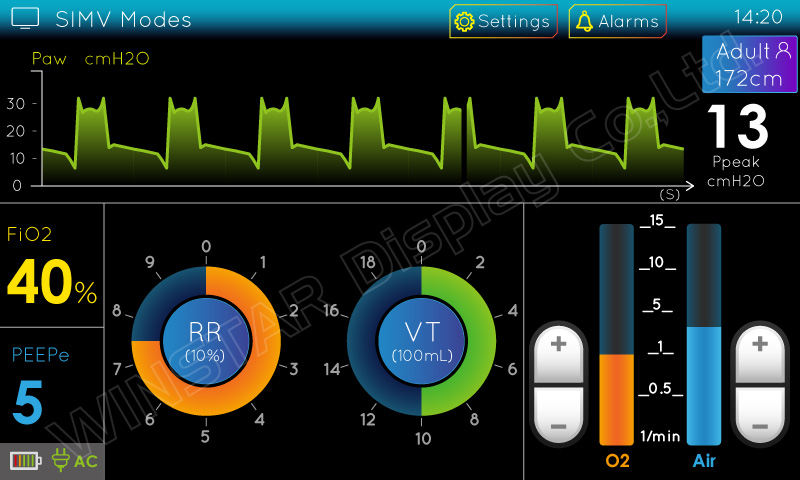
Example Layout (Medical application)
The screen layout described in this section is intended to demonstrate the settings of screen items that can be used in a Medical application situation.