DESCRIPTION
NEW 3nd generation 10.1” CAN BUS Smart Display which supports CUSTOMIZABLE CAN ID messages & GPIO.
10.1" Smart Display (Custom CAN ID series) Features
- + 12V power supply input, the power consumption is around 6W.
- Self testing after booting function.
- CAN bus communication interface.
- Supports Custom CAN ID protocol. Default baud rate is at 250KBps.
- Built in 16MB flash memory, store the font and Object Dictionary Data.
- Supports capacitive touch screen (CTP).
- Embedded buzzer controlled by Master Device.
- Demo set HOST can be used on multiple platforms, such as Computr (with USB to CAN Dongle), MCU, Raspberry Pi (with PiCAN2).
- GPIO PIN support.
- Design the UI without writing a line of code by Winstar GUI builder! (►Link to GUI Builder Introduction).
DRAWING
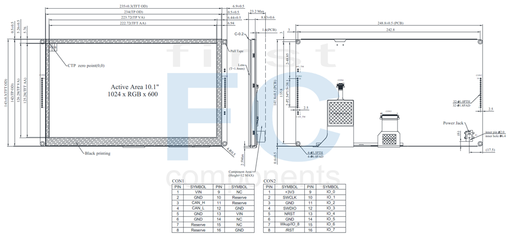
SPECIFICATIONS
General information
| Item | Standard Value | Unit |
|---|
| Operating voltage |
8C~28V dynamic |
Vdc |
| Communication Interface |
CAN bus |
Vpp |
| MCU |
STM32F746 |
N/A |
| Flash Memory |
16 |
MB |
| LCD display size |
10.1 |
inch |
| Dot Matrix |
1024 x RGB x 600(TFT) |
dots |
| Module dimension |
248.8(W) x 143(H) x 23.2(D) |
mm |
| Active area |
222.72 (H) x 125.28(V) |
mm |
| Dot pitch |
0.2175(W) x 0.2088(H) |
mm |
| Brightness |
Min:800; Typ:900 |
| LCD type |
LED, Normally Black, Transmissive |
| View Direction |
85/85/85/85 |
| Aspect Ratio |
16:9 |
| Touch Panel |
With CTP |
| Surface |
Glare |
Absolute Maximum Ratings
| Item | Symbol | Min | Typ | Max | Unit |
|---|
| Operating Temperature |
TOP |
-20 |
- |
+70 |
℃ |
| Storage Temperature |
TST |
-30 |
- |
+80 |
℃ |
Electrical Characteristics
| Item | Symbol | Condition | Min | Typ | Max | Unit |
|---|
| Supply Voltage |
VCC |
- |
8 |
12 |
28 |
V |
| Supply LCM current |
I |
- |
- |
720 |
- |
mA |
Bom
| Item | Description |
|---|
| LCM |
WF101-1024600JL#0SP8-FC |
| PCBA |
SV10010R100JB00N0106 |
Interface Pin Function
CON1 definition
| Pin | Symbol | Function | Remark |
|---|
| 1 |
+12V |
Power supply 12V input |
Input |
| 2 |
GND |
Power supply GND input |
Input |
| 3 |
CAN_H |
CAN bus D+ |
I/O |
| 4 |
CAN_L |
CAN bus D- |
I/O |
| 5 |
GND |
Power supply GND input |
GND |
| 6 |
GND |
Power supply GND input |
GND |
| 7 |
Reserve |
USB_D- |
Reserve |
| 8 |
Reserve |
USB_D+ |
Reserve |
| 9 |
NC |
- |
- |
| 10 |
Reserve |
USART RX interface(Reserve) |
Reserve |
| 11 |
Reserve |
USART TX interface(Reserve) |
Reserve |
| 12 |
GND |
Power supply GND input |
GND |
| 13 |
+12V |
Power supply12V input |
Input |
| 14 |
NC |
- |
- |
| 15 |
NC |
- |
- |
| 16 |
GND |
Power supply GND input |
Input |
CON2 definition
| Pin | Symbol | Function | Remark |
|---|
| 1 |
+3V3 |
3.3V power for JTAG interface |
Output |
| 2 |
SWCLK |
CLK pin for JTAG interface |
Input |
| 3 |
GND |
GND for JTAG interface |
Output |
| 4 |
SWDIO |
Data pin for JTAG interface |
I/O |
| 5 |
NRST |
Reset pin for JTAG interface |
Input |
| 6 |
GND |
GND |
Output |
| 7 |
Wkup/ IO_8 |
(PA0) for system Resume
from suspend (Reserve) |
WKup,ADC,Timer,Event,I/O |
| 8 |
/RST |
Reset (active Low) |
I |
| 9 |
IO_0 |
IO_0 |
ADC,DAC,Timer,Event,I/O |
| 10 |
IO_1 |
IO_1 |
ADC,Timer,Event,I/O |
| 11 |
IO_2 |
IO_2 |
ADC,Timer,Event,I/O |
| 12 |
IO_3 |
IO_3 |
RST,Timer,Event,I/O |
| 13 |
IO_4 |
IO_4 |
RST,Timer,Event,I/O |
| 14 |
IO_5 |
IO_5 |
ADC,Timer,Event,I/O |
| 15 |
IO_6 |
IO_6 |
RST,Timer,Event,I/O |
| 16 |
IO_7 |
IO_7 |
RST,Timer,Event,I/O |
Display Usage
Functional description
Smart Display can be used to display the coordinate, status and data information provided by the connected HOST device. Customers can configure the position coordinates they want to display in normal operation mode (Node ID = 0x7B).
The Display is designed to be easily connected to a controller network, and to operate with minimum setup or knowledge of the SDO configuration on the controllers.
Splash Screen
The default splash image is shown below:
This product is produced as a generic product. If you require a custom splash image for your application,
contact us to discuss.
Default Selection
Press the preferred application and hold for 3 seconds for the first time power on.
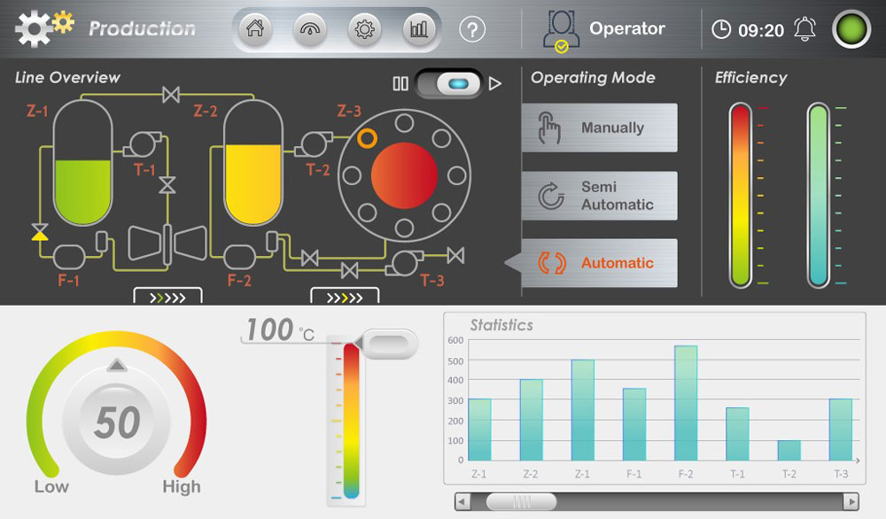
Example Screen Layout (Industry application)
The screen layout described in this section is intended to demonstrate the settings of screen items that can be used in an industry application situation.
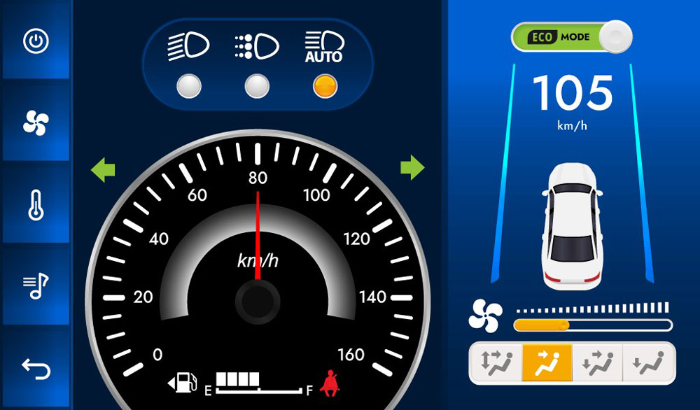
Example Screen Layout (Vehicle automotive)
The screen layout described in this section is intended to demonstrate the settings of screen items that can be used in a vehicle automotive situation.
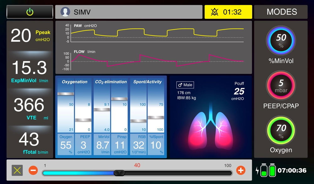
Example Screen Layout (Medical application)
The screen layout described in this section is intended to demonstrate the settings of screen items that can be used in a Medical application situation.
Specifiche di prodotto
|
Size
|
10.1" |
|
Resolution
|
1024x600 |
|
Active Area (mm)
|
222.72x125.28 |
|
Color
|
Full Color |
|
Power supply
|
12V |
|
Display Interface
|
CAN Bus + GPIO |
|
View Angle
|
IPS |
|
Sunlight Readable
|
High 601~1200cd/m² |
|
Frame
|
Yes |
|
Touch Panel
|
Capacitive |
|
O. Temperature (°C)
|
-20~70 |
|
Preferred - Not Preferred
|
Preferred |